Q&A With HELU: Grounding vs. Bonding

One of the first lessons new electricians learn is that electricity will always look for the path of least resistance to get to the ground. The terms grounding and bonding are used every day by electricians, maintenance engineers and technicians. While they seem interchangeable, they are actually two distinct electrical installation protocols when it comes to the National Electrical Code (NEC) and installing electrical equipment. Regional Sales Manager Warren Lyles discusses this topic from questions he has heard in the field.
Q: What is grounding?
A: Grounding is accomplished by connecting neutral conductors to the electrical grounding system at the electrical service entrance of a facility, which is connected to the earth by means of one or more grounding electrodes, which vary between ground rods, plates, buried metal water pipe, well casings, rebar or structural building steel. The act of grounding is so important that the NEC Code-Making Panel actually considered replacing the term “grounding” with “earthing”, predominantly used in Europe, to provide a term that offered better clarification.
The purpose of grounding is to drain transient voltages (such as those caused by lightning, leakage from electrical equipment or fallen power lines) out of the system and to control the build-up of static charges that can damage sensitive electronic equipment. Since the earth is an infinite absorber of electrons, electrodes driven into or buried in the ground is the standard method.
Ground wires are easy to find in electrical systems because they are either bare copper wire or a copper conductor with green or green-yellow striped insulation.
Q: How does grounding or a grounding system work?
A: When an electrical system functions normally, ground systems don’t carry a current because all electricity in the closed system is handled by the hot and neutral wires. However, in the case of a surge, fault, or other overcurrent situation, electricity wants to travel the path of least resistance. When this happens, the current travels through the low-resistance ground wire back to the grounding system, arcs to a circuit’s ground paths, or proceeds through the circuit and possibly damaging the circuitry along its path. A ground fault breaker will detect lost current and trip. Surge-protecting modules will divert power surges to ground paths, which is usually the case from lightning or power surges on the grid. Overload current will trip a standard breaker, which terminates the circuit and prevents electricity from flowing to avoid damage to the electrical system or even worse, a fire. Grounding systems also can be a conduit for shield current for cables with EMI shielding (foils or braids) and a ground path for leakage current from motors.
Q: What is electrical bonding?
A: Bonding is the act of mechanically connecting two or more conductive materials together to establish a conductive path between them. By bonding normally non-current carrying objects that are part of the electrical installation (such as raceways, metallic connectors and enclosures) to the grounding system, it ensures that they cannot become energized. If a fault occurs in a properly bonded system, the current will trip the overcurrent device as quickly as possible. Bonding also supplies a route for static electricity and induced voltages to safely drain, reducing the possibility of a shock hazard. It is possible to “bond” components together without ever grounding them.
Q: Does the shield on a shielded cable need to be grounded or bonded?
A: A shield is generally an electrically conductive substance that is intended to protect the connected devices from electrical noise. Cables can be both a source of electric noise as well as a receiver. As a source, cables can radiate signals to other cables and even act as an antenna that radiates noise. The cable can also receive these signals from other cables and cause them to spread through your factory floor.
The cable shielding and its termination must provide a low-resistance path to the ground. The drain wire and cable braid/foil are both parts of a cable shield and are electrically connected. A shielded cable that is not properly bonded lowers the shielding effectiveness and can allow electrical noise to interfere with surrounding instrumentation, wireless and industrial devices.

Q: What is noise in an electrical system?
A: Electric noise is a rather simplistic term for electromagnetic interference (EMI). It is a disturbance in an electrical system that causes changes in voltage or current. In the case of a data path, these effects can range from an increase in error rate to a total loss of data. When switching any big load of power, such as those required in huge transformers, powerful heaters or electric motors, it is enough to trigger a noticeable amount of EMI.
When electrical noise occurs, the current amplitude isn’t that high, in fact, it’s very low, but voltage spikes can easily damage your electronic devices if not remedied as soon as possible.

Q: How are electrical systems typically bonded and grounded?
A: There are a variety of options to properly bond and ground an electrical system and includes such items as compression grounding lugs, grounding straps, EMC cable glands, or single conductor green-yellow Class 5 finely stranded copper cables to help keep a facility up and running.
- Compression grounding lugs are conductive fasteners that are used to secure the grounding conductor. Grounding conductors typically consist of copper wires. They are used to provide a safe and alternate path for excess electricity. Lugs that are properly crimped to the cable are the best connections to make for standard low-voltage systems. When these lugs are properly positioned and bolted together, they will provide a good, long-lasting connection and will save you from unexpected downtime and failure. The benefits of a good electrical connection far outweigh the time savings of using a mechanical lug on the initial installation.
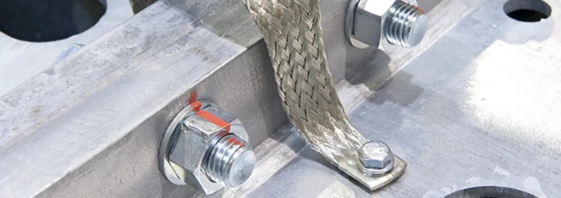
- Copper grounding straps are comprised of a thin, tinned copper wire braid that connects the enclosures to a suitable ground path. They can extend the service life of components by dispersing the electromagnetic currents. They are maintenance-free, improve installation efficiency, and have good heat dissipation. When copper grounding straps are used in applications such as the automotive industry, robotic automation and in switching cabinets, they can reduce the damage of stress and deformation to the power supply systems.
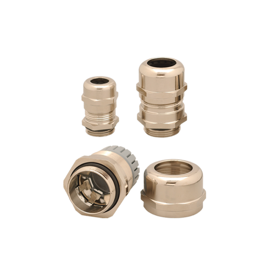
- EMC cable glands contact the cable shield and, in addition to serving as a strain relief, provide electromagnetic protection by bonding the shield to the enclosure. They are normally made of stainless steel or nickel-coated brass.
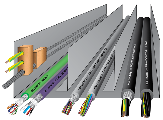
- In North America, the preferred method for using a green-yellow ground is to cable this conductor with the other conductors when there are two or more, unless the application requires a separate, external ground cable. UL requires this method for most of its approvals. In Europe, flexible, green-yellow single conductor cables are often combined with grounding/potential equalization blocks and stranded, tinned copper to reduce electromagnetic interference for cables that are installed in trays to avoid any potential disruptions.
ARTICLE DOWNLOAD
Click here to view this article in our digital download center.
